PM DC Motor
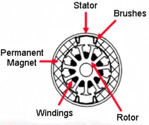
The Brushed DC Motor gets its name from the "brushes" used for commutation. Here are some key points about the brushed DC motor:
- Typically the rotor, also known as an armature, has windings on it terminated on to a commutator
- Brushes make and break contact with commutation segments, thus commutating power to the armature
- The stator, or outer cylinder, of a permanent magnet DC motor will have two or more permanent magnet pole pieces
- The opposite polarities of the energized winding and the stator magnet attract causing the rotor to rotate until it is aligned with the stator
- Just as the rotor reaches alignment, the brushes move across the commutator contacts and energize the next winding
Brushed DC motors are easy to control because speed and torque are proportional to the applied voltage/current. The rotor is heavy due to windings on the armature, more inertia makes it more difficult to start/stop. Heat is generated in windings on the rotor, and is more difficult to remove.
Key Characteristics of the Brushed DC Motor
- Good controllability: on/off, proportional
- Linear torque/current curve
- Speed proportionate to voltage applied
- Requires maintenance
- Low overloading capability
- Low heat dissipation
Click image to enlarge
How it Works
The speed of the brushed DC motor is controlled by controlling the armature voltage, and the torque by the armature current, that is, the flux and the torque can easily be controlled separately. This is the main principle on which all the modern AC control methods now rely. The first DC motors were controlled with some chopper technology, such as the Pulse Width Modulation (PWM). Network-connected thyristor bridges were mainly used in higher power ranges, typically in a variety of applications.
Brushed DC Motor Control
Input:
- Torque
- Speed
- Position and/or direction
- Inputs can be analog voltage, potentiometer, switches
or digital communications
Control:
- Basic I/O for firmware PWM or on/off control
- Comparators for over-current detection
- Capture/compare/PWM
- Enhanced capture/compare/PWM
- Higher resolution motor control PWM
- Low side drive control
- High side drive control
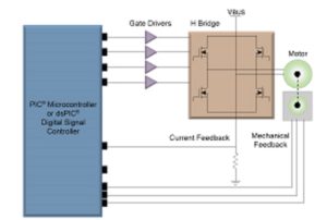
- H-Bridge drive control
Feedback:
- Optical encoder
- Limit switches
Low Side Configuration:
This drive can control a brushed DC motor in one direction and is often used in safety critical applications.
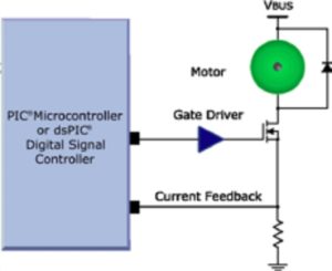
High Side Configuration:
Lowest cost drive technique.
Most applications can simply use an output pin from the dsPIC® DSCs/PIC® microcontroller to turn the MOSFET on.

Design Flowchart
